What does 6 H and 6 g mean in the general designation of threads?
In the end, they must fit together: the screw and the nut. In the past, this was regulated in such a way that each internal thread had its own matching external thread. Then came the industrial age and generally binding rules for technology were established (standard). And thanks to this standard, screws from England now fit nuts from Germany. A part of this standard also defines the tolerance. It is understood here as the permissible deviation from the standard dimension without endangering the system as a whole. An example is the specification 20 +1/0.5.

This means: the measure can be between 21 and 19.5. The tolerance is 1.5. Tolerance specifications are necessary because perfect accuracy is not technically feasible and is not functionally desirable.
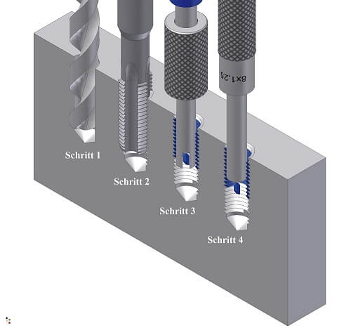
After all, the aim of thread cutting is to create external threads and internal threads that fit together. In the language of technology this is called fit. And to ensure that this fit works, the following has been defined in the screw standard. The dimension of the screw should be below the nominal dimension, the dimension of the nut should be above the nominal dimension. And the tools that produce the screw and nut threads must follow this logic, albeit within narrower tolerance ranges than the screw standard.
Small letter = external thread |
Large letter = internal thread
6 H is therefore the designation for the tolerance of the taps, with which an average fit between screw and nut is produced. The number stands for the degree of tolerance and the letter for the position of the tolerance field. For internal threads, the tolerance field positions G and H are standardized and for external threads the tolerance field positions e, f, g and h.
In our example 6 H, this is a medium tolerance class for standard threads from M1.6. If you want to name a fit between threaded parts, the designation is, for example: M 6 – 6H/6g.
(small letter = external thread, large letter = internal thread)
So far so good, but what on earth is behind Tolerance Grade 6 and what is the location of the tolerance field? All this is defined in DIN ISO 965-1.
Let’s stay with our example: the capital letter H defines the position of the tolerance field for internal threads with basic dimension 0, i.e. the tolerance field lies on the zero line. It is different for the external thread g: the basic dimension is negative, i.e. the tolerance zone is always below the zero line. In the technical definition, this now corresponds to what we have already seen above. The dimension of the die is always below the nominal dimension. In order for the fit to work, the tolerance field must always be negative, i.e. it must always be below the zero line.
Now what about the 6?
DIN ISO 965-1 also provides information here. To ensure that the system of tolerance grades is consistent for the various pitches and outside diameters, the tolerances have been defined in tables. And a number has been assigned to each of them. For the internal thread there are the numbers 4 5 6 7 8 for the degrees of tolerance, for the external thread 4 6 8. The larger the number, the greater the degree of tolerance.
Finally, one question remains to be clarified: what happens if the information on the tolerance is missing? The standard also provides clear information. Then the tolerance class is assumed to be medium with the following tolerance classes: 6 h for threads M 1.6 and larger for internal threads and 6 g for threads M1.6 and larger. But that was already known.
We recapitulate.
The designation for the tolerance class contains an indication of the tolerance class for the flank diameter, followed by the tolerance class for the core diameter of the internal thread or the outside diameter of the external thread.
Each specification of a tolerance class consists of:
• A number for the tolerance grade,
• a letter for the tolerance field position, namely capital letters for internal threads and small letters for external threads.
If the two designations of the tolerance classes for flank and core diameters of the internal thread (or for the external diameter of the external thread) are the same, it is not necessary to repeat the abbreviations.
External thread
Standard thread with a nominal diameter of 10 mm
Tolerance classes for flank and outside diameters
Internal thread
Standard thread with a nominal diameter of 10 mm
Tolerance classes for flank and outside diameters

Technical table: tolerance classes for the surface condition